Privia Security was chosen as one of Türkiye's fastest growing companies!

Privia Security was chosen as one of Türkiye's fastest growing companies!

DITTO DX Forensic – Today, digital data recovery and forensic analysis processes are becoming increasingly complex and challenging due to the rapid proliferation of digital devices and the growing volume of data.
As a result, the effectiveness and reliability of these processes are of paramount importance.
Digital data recovery experts and forensic analysts need reliable and efficient tools to collect data from all types of digital devices. This is precisely where the DITTO DX Forensic device plays a critical role in digital data recovery and analysis.
This device makes data collection and analysis processes far more secure and efficient.
DITTO DX Forensic is a device developed to accelerate and improve the reliability of digital data recovery processes. With the features it provides, users can collect and analyze data more effectively.
DITTO DX Forensic is a portable device designed to facilitate digital data recovery and analysis operations. It is used by data recovery specialists, cybersecurity professionals, and forensic analysts to securely and effectively collect digital evidence.
DITTO DX Forensic accelerates digital data analysis processes while preserving data integrity, enabling the acquisition of evidence that can be used in forensic proceedings.
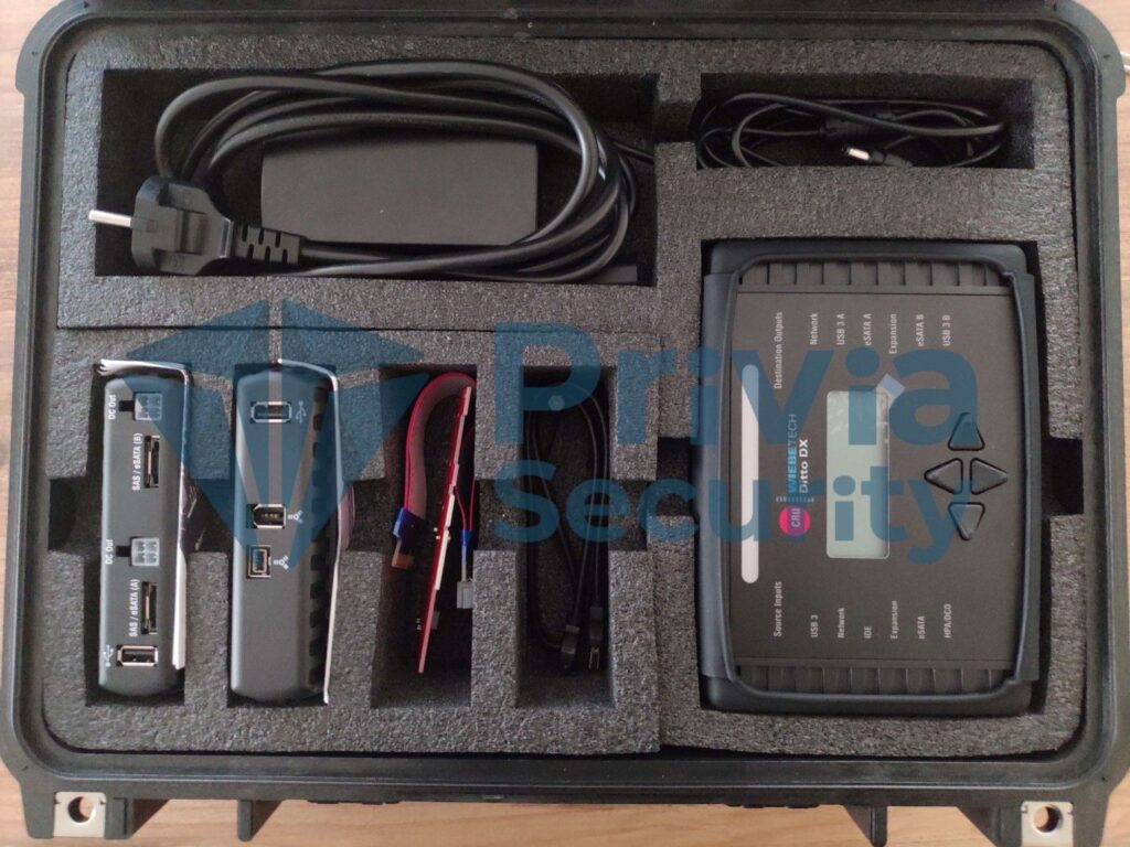
| Ditto DX Forensic FieldStation Device | 1 |
| SAS -> eSATA + MiniFit Power Cable Adapter | 3 |
| IDE Cable | 1 |
| 12V Power Supply | 1 |
| Power Cable | 1 |
| Legacy Power -> MiniFit Power Adapter | 1 |
| Ethernet Cable (RJ45) | 1 |
| Velcro Cable Wrap | 1 |
| eSATA Cable | 2 |
| SD Card | 1 |
| Ditto DX External Fan | 1 |
LightBar Status Indicator by Color:
| COLOR | STATE | DESCRIPTION |
|---|---|---|
| Blue | Solid | Idle. |
| Magenta | Solid | An operation is in progress. |
| Green | Solid | An operation completed successfully. |
| Red | Solid | An error was detected, or the running action was cancelled by the user. |
| Yellow | Solid / Blinking | The processor is approaching the recommended maximum temperature. CRU recommends using the Ditto DX external fan. The running action has been paused by Ditto DX due to a temperature issue and will resume from where it left off once the temperature drops to the recommended level. |
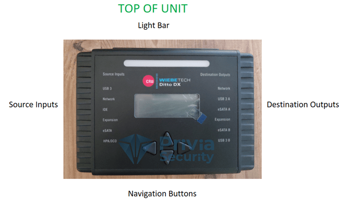
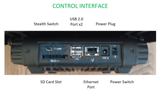
The control interface section of the Ditto DX Forensic FieldStation features a power button, a power input for the 12V power supply, two USB ports for a keyboard or Wi-Fi adapter, an RJ45 Ethernet port for accessing the Ditto DX browser interface (Section 3), and a stealth button that turns off all lights and activates night-vision mode (Section 10).
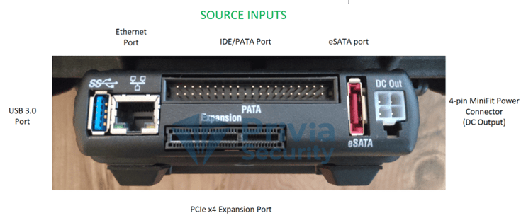
Suspect drives or devices are connected to the Ditto DX’s source input section. All source inputs are write-protected to prevent any modifications. The source input section includes a USB 3.0 port, one RJ45 Ethernet port, an IDE/PATA disk port, one eSATA port for SATA drives or eSATA devices, and a PCIe x4 port for the Ditto DX adapter kit or SAS/FireWire expansion modules.
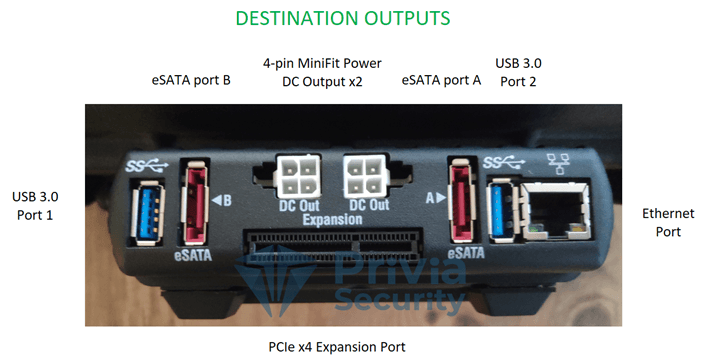
The Ditto DX’s destination output section is used for acquired data. Destination output connections include two USB 3.0 ports, an RJ45 Ethernet port, two eSATA ports for SATA or eSATA devices, and one PCIe x4 port for the adapter kit and expansion modules mentioned above.
NOTE: It is recommended to power off the device before connecting another device to the Ditto DX Forensic FieldStation. Failure to do so may cause damage to the Ditto DX device or data loss and damage to connected drives.
The Ditto DX can be operated from the front panel or via the browser interface.
Accessing Over a Network:
Configuring Using DHCP:
Configuring Using a Static IP:
The main screen is the first screen seen after logging in, and most operations are performed from here.
DITTO DX Forensic offers a range of features that make users’ workflows more efficient. These features simplify the collection and analysis of digital evidence.
The “Action” panel is where all operations such as starting or cancelling a clone are performed. Clicking the “Comment” button allows you to add a note to the log. The “Configure” [0] button is used to change default settings for each operation. The same action can also be performed from the “CONFIGURE” [1] section in the top panel.
Clone Source Disk
Ditto DX can write an exact copy of the source disk to one or two destination drives. Additionally, during the cloning process, Ditto DX can calculate the hash of the source disk using MD5, SHA-1, SHA-256, or MD5 & SHA-256 algorithms.
Follow these steps to clone a disk:
The source and destination drives do not need to be of the same type, but the destination disk must have greater capacity than the source disk. Cloning results can be viewed in the “System Log” section at the bottom of the main screen or by clicking the “LOGS” button in the top panel.
Physical Image Source Disk
The Ditto DX Forensic FieldStation can write an E01 or DD format image of the source disk to one or two destination drives. NOTE: Ditto DX can also calculate the hash of the source disk using MD5, SHA-1, SHA-256, or MD5 & SHA-256 algorithms during imaging.
For best performance, NTFS is recommended for Windows, HFS+ for Mac, and XFS for Linux.
The source and destination drives do not need to be of the same type, but the destination disk must have greater capacity than the source. Using E01 Compression can help with this. Imaging results can be viewed in the “System Log” section at the bottom of the main screen or via the “LOGS” button in the top panel.
Logical Image Source Disk
A logical image allows an investigator to quickly examine the contents of a hard drive and access only the files relevant to the investigation, in formats such as L01, ZIP, TAR, or LIST. Follow these steps to capture a logical image:
The “Logical Image Source Disk” operation generates a report of selected folders and files from the source disk, along with file sizes and any errors encountered during the process.
If “Manual Select” is chosen, follow these steps:
Imaging results can be viewed in the “System Log” section at the bottom of the main screen or via the “LOGS” button in the top panel.
Manual Select: Activates the “Select Files & Dirs” button, allowing you to manually select the files for the logical image.
All Files and Dirs: Images all files and folders.
All Except Windows: Images all files and folders except the Windows folder.
All Except Windows and Programs: Images all files and folders except the Windows, Program Files, Program Files (x86), and ProgramData folders.
All Users Windows: Images all Windows “Users” folders.
All Temporary Windows: Images the Windows/Temp and Temp folders.
All Except Swap and Hibernate: Images all files and folders except hiberfil.sys, pagefile.sys, Win386.swp, and 386part.par.
All Media Files: Images all .avi, .jpeg, .jpg, .wav, and .mov files, all files with extensions starting with “.mp” (.mpeg, .mp4, .mp3, etc.), and all files with extensions starting with “.m4” (.m4a, .m4v, etc.).
All Office Files: Images all .txt and .pdf files, and all files with extensions starting with “.doc,” “.xls,” and “.ppt” (.doc, .docx, .xlsx, .pptx, etc.).
All Financial Files: Images all .ifx, .ofx, .qfx, .qif, and .tax files.
NOTE: You can add a customized Logical Image Mode profile to the dropdown menu.
A Physical Image is a complete copy of the device — the most comprehensive image available. Physical forensic images also capture deleted partitions and file fragments, and provide access to encrypted and deleted data. The advantage is full access to device files and logs; the disadvantage is that it requires greater resources.
A Logical Image, on the other hand, captures all files visible to the user on a disk. It does not recover deleted files and cannot retrieve data from deleted sections of the device. It also does not collect file fragments. The advantage is that it requires fewer resources; the disadvantage is that it provides no information about deleted files.
File fragmentation refers to a file being scattered across a hard drive rather than stored in a single contiguous location. Fragmentation occurs when information is deleted from a hard drive, leaving small gaps that are filled with new data as it is saved. If the gaps are too small for new data, the remaining portion is stored in other available spaces.
This operation simultaneously clones the source disk to the first destination drive and writes a disk image to the second destination drive. (This operation requires two destination drives.) Ditto DX can also calculate the hash of the source disk during this process using MD5, SHA-1, SHA-256, or MD5 & SHA-256 algorithms. The hash type can be selected from the “System Settings” panel on the main screen.
Follow these steps to clone and physically image simultaneously:
Results can be viewed in the “System Log” panel at the bottom of the main screen or via the “LOGS” button in the top panel.
An image taken from one disk can be restored to another. The image file must be in DD or E01 format. The destination disk must be the same size as or larger than the source disk.
Follow these steps to restore a disk:
The destination disk must be larger than the source disk.
Ditto DX Forensic FieldStation can erase a drive connected to the destination section according to the selected erase mode. The available erase modes are:
Follow these steps to erase a drive:
Format After Erase
Ditto DX can be set to format the drive after an erase operation. Go to the Erase tab in the Configure screen and check the format after erase option for each erase mode.
Ditto DX Forensic FieldStation can calculate the hash of any drive connected to either the source or destination side. Hash values are recorded in the system log. Available hash formats are MD5, SHA-1, SHA-256, MD5&SHA-1, and MD5&SHA-256.
Follow these steps to hash a drive:
When the operation completes, the hash value can be viewed in the System Log panel on the main screen.
Ditto DX Forensic FieldStation provides S.M.A.R.T. and hdparm information about any drive connected to either the source or destination side, without requiring a clone or imaging operation.
Follow these steps to take a snapshot of a drive:
View the results in the System Log panel on the main screen.
NetView is a network tool that discovers machines on a network and scans for specific services running on those machines. This feature helps investigators locate physically hidden computers or determine whether any machine is being used as a data storage device that can be imaged by the Ditto DX.
The Investigation Info panel groups related pieces of information that can be used to create specific directories or files. Clicking the Edit button allows modification of the investigator, case number, evidence number, description, notes, base directory name, and base file name for E01 or DD images. Invalid characters are filtered out.
Click the green plus button to open the “Add User Defined Field” window. You can add as many fields as needed. Each added field requires a title, XML tag, and value. The title defines the name displayed in the Ditto DX Forensic FieldStation browser interface. The XML tag is visible only in configuration and log files. To delete user-defined fields, click the green minus button.
The most commonly used configuration settings are displayed here. These are the default settings used for operations performed in the “Action” panel. Click the Configure button to change these settings.
Displays the progress percentage of the current operation or the availability status.
Displays connected drives. Click the green button to view drive usage rates. The Target mode button allows you to present devices connected to Ditto DX as iSCSI disks over a network. iSCSI (Internet Small Computer System Interface) is a method for connecting network data storage devices to each other over TCP/IP, enabling disks in a storage device to be used across networked computers as if they were local virtual disks.
The “Source Network” and “Destination Network” buttons are used to connect iSCSI devices and to mount NFS and SMB shares. For more information, refer to Section 11.
To view and download disk contents, or to select files and folders for a logical image, click the partition number. A window will appear where you can browse files and folders.
To view a drive’s data in hex format, click the drive name under the Port column, then select HexView. To view a partition’s hex data, click the partition number and select HexView.
To view snapshot information for a drive, click the drive name under the Port column and select Snapshot.
Displays operations performed by Ditto DX. Click the Comment button to add entries to the System Log. If no SD card is inserted, all logs captured in temporary memory since the last power-on are listed. These logs are deleted when the Ditto DX is powered off. If an SD card is inserted, this panel lists all operations recorded on the card. To view the log details of a specific operation, click the links under the Message column. Links will be in the format “S_yyyymmddhhmmss” — for example: S_20140819145247.
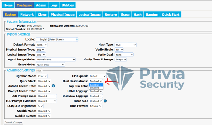
The Configure screen allows you to adjust Ditto DX functions to suit your needs. You can access this screen by pressing the Configure button next to the Home button.
The System tab allows you to change the settings listed below. This information is also displayed in the System Settings panel on the main screen.
The “Network” tab allows you to view and customize the settings listed below. If unsure about changes, consult your network administrator. When finished, press Commit Changes to save.
Allows you to change the name displayed for the Ditto DX Forensic FieldStation on a network. Host names are not case-sensitive but must begin with a capital letter.
Displays the MAC address and network mode of the source Ethernet port. Select DHCP or Static IP to set the network mode. The “Remote Accessibility” dropdown configures whether the Ditto DX responds to any network traffic over the Ethernet port.
Displays the MAC address and network mode of the destination Ethernet port. Select “Server,” “Client DHCP,” or “Client Static IP” to set the mode.
Server: Configures the Ditto DX Forensic FieldStation as a server. Useful when connecting an iSCSI device to the destination Ethernet port (see 11.3.2) or when connecting Ditto DX directly to your computer rather than to an office network. Do not connect a configured server to another network, as this causes network conflicts.
Client DHCP: Automatically configures the destination Ethernet port to connect to the current network.
Client Static IP: Allows manual configuration of the destination Ethernet port to connect to the current network.
Displays the MAC address and network mode of the control Ethernet port. Select “Server,” “Client DHCP,” or “Client Static IP” to set the mode. The same Server, Client DHCP, and Client Static IP options described above apply here as well.
The “Wi-Fi Network” section allows configuration of a Wi-Fi adapter plugged into any USB port on the Control Interface. It also displays the port’s MAC address. Adapters with Atheros and some Realtek chipsets are supported. “Wi-Fi Mode” lets you choose between connecting to an existing Wi-Fi network and acting as a hotspot. Hotspot mode is useful when Ditto DX is within range of a wireless network but operating separately from it, or when no wired network is available.
Select “Client Mode” to connect to an existing network, or “Hot Spot Mode” to use the Ditto DX as a hotspot.
Client Mode: Check “Status: Auto Check” to automatically connect to the defined wireless network. Then select Client DHCP to automatically configure the Wi-Fi adapter, or Client Static IP for manual configuration.
Hot Spot Mode: Check “Status: Auto Check” to activate hotspot mode as soon as the Wi-Fi adapter is inserted. The default settings will work in most environments with some exceptions.
NOTE: You may need to comply with your country’s wireless radio frequency regulations. Select the 2-digit country code from the “Regulatory Domain” dropdown to restrict broadcast to the permitted frequency range. Do not connect Ditto DX to a wired network while it is operating as a hotspot, as this will cause network conflicts.
The Clone tab allows you to change the following settings for disk cloning operations, including the “Clone & Image Source Disk” operation. Press Commit Changes when finished.
Source HPA/DCO: Specifies whether the cloning operation logs the presence of an HPA (Host Protected Area) or DCO (Device Configuration Overlay). Options include temporarily bypassing the HPA, showing the HPA, or showing both HPA and DCO.
Fill to End of Disk: When checked, fills the end of the disk with zeros.
Reset After Fill: Selects whether an HPA or DCO is set on the destination disk so that its capacity matches the source disk’s capacity.
Buffer Size: Adjusts the buffer size during the cloning operation. Minimum is 512 KB; default of 1 MB is sufficient for most operations.
Exit when a bad sector is encountered: Ditto DX stops the cloning operation if a bad sector is found on the source disk.
The Physical Image tab allows changes to physical imaging settings, including for the “Clone & Image Source Disk” operation. Press Commit Changes when finished.
Click the E01 tab to view E01 image settings.
Typical Settings:
Advanced Settings:
Click the DD tab to change DD image settings.
Typical Settings:
Advanced Settings:
The Logical Image tab allows changes to settings for the “Logical Image Source Disk” operation. Press Commit Changes when finished.
Click the L01 tab to change L01 image settings.
Typical Settings:
Advanced Settings:
Click the ZIP or TAR tab to configure settings for either logical image type.
The Restore tab allows you to view and change settings for the Restore Physical Image operation.
Typical Settings:
Fill to End of Disk: Fills the end of the disk with zeros.
Reset After Fill: Selects whether an HPA or DCO is set on the destination disk to match the source disk capacity.
Advanced Settings:
Buffer Size: Minimum 512 KB; default 1 MB.
Ditto DX allows you to view and configure settings for how disks are erased.
| ERASE MODE | DESCRIPTION |
|---|---|
| Clear Partition Table | Erases partition table data on the disk (writes zeros to the first 16 KB of the disk). |
| Quick Erase | Provides a fast operation by writing all zeros. |
| LBA/Offset Pattern | Writes byte/LBA information to each sector. |
| Custom Erase | Fills the disk with zeros or a user-defined pattern. |
| Secure Erase Normal | Runs the disk’s own normal secure erase function. |
| Secure Erase Enhanced | Runs the disk’s own enhanced secure erase function. |
| DOD Clear | Applies the U.S. Department of Defense clear standard — writes all zeros to the disk in a single pass. |
| DOD Sanitize | Applies the DoD sanitize standard: first writes the pattern 0xAAAAAAA, then its hex complement (0xFF555556), followed by an unclassified pattern. |
| NIST800-88 Clear | Applies the NIST 800-88 clear standard by writing all zeros. |
| NIST800-88 Purge | Applies the NIST 800-88 purge standard by running the disk’s internal secure erase normal function. |
The Hash tab allows you to view and configure settings for all hash operations.
Buffer Size: Minimum 512 KB; default 1 MB.
Exit when a bad sector is encountered: Ditto DX stops the operation if a bad sector is found on the source disk.
The Naming tab lets you configure file and folder naming settings for imaging operations.
The Quick Start tab allows you to change the default settings for operations displayed on the Ditto DX screen when Quick Start mode is active (enabled in the System tab). For example, you can select permitted source types and default source partitions for imaging operations.
Use this screen to manage user accounts and set permissions for each user. You can add, delete, and update permissions for existing users. To add a user, press Add User, enter the username, full name, and password, select the required permissions, and click Commit Add to confirm.
The Logs screen provides information about operations performed by Ditto DX. The Action Logs section includes a timestamp, operation type, who performed the operation, and a link to detailed information. Clicking the link opens a detailed report, including disk information before and after the operation.
The Utilities screen allows you to perform various tasks such as firmware upgrades, importing custom configuration files, remotely rebooting the Ditto DX, factory reset, and date/time updates.
Firmware updates are published on CRU’s website at https://wiebetech.com/software/ditto-family-firmware/downloads-for-ditto-dx/. Firmware can be upgraded in three ways:
Method 1: Paste a link
Method 2: Download to your computer
Method 3: Load from USB drive
Save Config: Click this button to save the current configuration. A screen will appear allowing you to set the configuration file name.
Load Config: After clicking Load Config, select the .xml file to import. Once confirmed, the imported settings will overwrite the current settings.
The Ditto DX can be operated using only the front panel and directional buttons, without an external computer. Operations such as cloning, physical imaging, logical imaging, simultaneous cloning and imaging, erasing, hashing, viewing information about connected disks, and taking snapshots can all be performed from the front panel. The admin account can manage front panel access permissions from the browser interface.
You can use the directional buttons on the front panel, or alternatively connect a keyboard to the USB port on the Control Interface. Arrow keys on the keyboard perform the same functions. Press Enter to confirm the current action.
You May Be Interested In These